
Description About the Project:
An IoT-based irrigation system is a smart and automated solution that leverages Internet of Things (IoT) technology to optimize the irrigation process in agriculture or landscaping. The system integrates sensors, actuators, and communication devices to monitor and control the irrigation process remotely.
Key components and features of an IoT-based irrigation system may include:
Soil Moisture Sensors: These sensors measure the moisture content in the soil. When the soil moisture falls below a certain threshold, it triggers the irrigation system to water the plants.
Weather Stations: Integration with weather stations allows the system to consider external factors such as temperature, humidity, and precipitation in determining the irrigation schedule. This helps in avoiding unnecessary watering during rainy periods.
Mobile Application: Users can control and monitor the irrigation system through a dedicated mobile application. This application provides a user-friendly interface to remotely irrigation system, view real-time data, and receive notifications.
Requirements:
- ESP32 LEARNING BOARD V1.0
- SOIL MOISTURE SENSOR
- DTH11
- DC PUMP
- 12V ADAPTOR
- I2C LCD(Inbuilt in Board)
Connection Layout:
| I2C LCD(Inbuilt) | ||
| LCD | ESP32 BOARD | |
| 1 | SDA | GPIO21 |
| 2 | SCL | GPIO22 |
| 3 | VCC | Vin |
| 4 | GND | GND |
| DTH11 | ||
| DTH | ESP32 BOARD | |
| 1 | OUT | SNS2-D4 |
| 2 | VCC | +3V3 |
| 3 | GND | GND |
| SOIL MOISTURE SENSOR | ||
| SENSOR | ESP32 BOARD | |
| 1 | A0 | P1-D35 |
| 2 | VCC | +3V3 |
| 3 | GND | GND |
| DC-PUMP | ||
| PUMP | ESP32 BOARD | |
| 1 | -ve | GND |
| 2 | +ve | RLY-(NO) |
| 3 | +5V | RLY-(COM) |
Connection diagram:
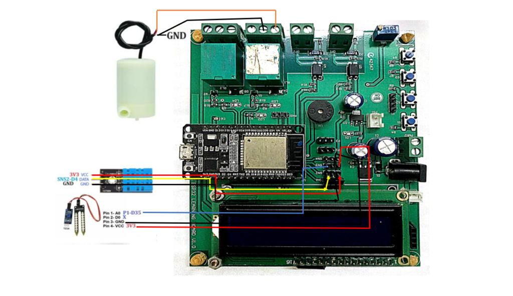
Procedure:
Step1: Firstly we require all these component connected as per circuit diagram (referred to Fig1).
Step2: The it is require to download and install the Arduino IDE 2.2.1 or above version (link Given Below).
Link: https://www.arduino.cc/en/software
Note: Choose the appropriate version of this software as per your system configuration.
** The Arduino IDE (Integrated Development Environment) is a user-friendly software platform for programming Arduino microcontrollers. Designed for simplicity, it enables users to write, compile, and upload code to Arduino boards seamlessly. With a straightforward interface, the IDE caters to beginners and experienced developers alike, offering a versatile environment for creating interactive electronic projects. It supports C and C++ programming languages, providing a wide range of libraries for various sensors and modules. The Arduino IDE plays a pivotal role in the open-source Arduino ecosystem, fostering innovation and making hardware programming accessible to enthusiasts and professionals in the fields of electronics and IoT.**
Step3: Add Esp32 Board to Arduino IDE that helps us to Program our ESP32 Learning Board with the IDE.
*you can follow the tutorial from Random Nerd to add the ESP32 Board with IDE
Link: https://randomnerdtutorials.com/installing-the-esp32-board-in-arduino-ide-windows-instructions
Courtesy: https://randomnerdtutorials.co *
** The ESP32 is a versatile and powerful microcontroller board widely used in IoT and electronics projects. Developed by Espressif Systems, it features a dual-core processor, Wi-Fi, Bluetooth, and a rich set of peripherals. With its ample processing power and connectivity options, the ESP32 excels in applications ranging from home automation to industrial IoT. The board supports the Arduino IDE and is well-documented, making it accessible for both beginners and experienced developers. Its low power consumption and cost-effectiveness contribute to its popularity, while the integrated capabilities, such as real-time clock and cryptographic functions, enhance its suitability for a broad spectrum of projects.**
Step4: Download and Install CP210x USB to UART Driver to establish the coomnication between ESP32 and System(link given below).
Link: https://www.silabs.com/developers/usb-to-uart-bridge-vcp-drivers
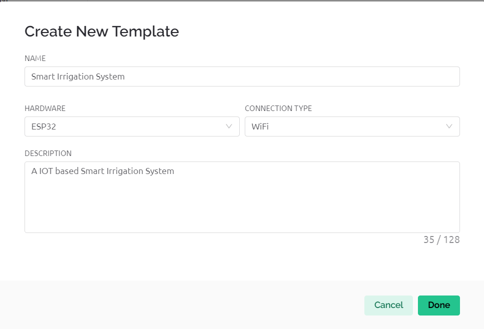
Step5:Go to https://blynk.io and create account or Log in (if already created).
Start doing the following:
Go to Developer Zone AND create a new template and name the project as “SMART IRRIGATION SYSTEM” ,Choose hardware as ESP32, connection type as”WIFI”. (shown in fig 2.)
Go to developer zone ->Datastream
Create 4 data streams of type virtual pins with following specifications
- Soil Moisture
Pin: V0
Datatype: DOUBLE
Min: 0
Max: 100
Default value: 0
- Temperature
Pin: V1
Datatype: DOUBLE
Min: 0
Max: 100
Default value: 0
- Humidity
Pin: V2
Datatype: DOUBLE
Min: 0
Max: 100
Default value: 0
- Button
Pin: V3
Datatype: INTEGER
Min: 0
Max: 1
Default value: 0
Now move to Tab WEB DASHBOARD and drag and drop 3 Gauge and 1Switch as shown in fig3.
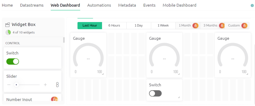
Now Select gauge 1 and name it as soil moisture and choose datastream type as Soil Moisture.
Then Select gauge 2 and name it as Temperature and choose datastream type as Temperature .
Then Select gauge 3 and name it as Humidity and choose datastream type as Humidity.
Then Select Switch and name it as Button and choos datastream type as Button.
Now Save the changes.
Now go to devices->New devices.->from Templates
Select template as Smart Irrigation System and device name as Smart irrigation system
Then a window pop up copy BLYNK_AUTH_TOKEN from there it is required in code at step 7.
Step6: Install Blynk IOT app in your smart phone.
Link: https://play.google.com/store/apps/details?id=cloud.blynk
Sign in with the same email as in web dashboard.
Select developer option symbol and select template SMART IRRIGATION SYSTEM.
Add 3 GAUGE and 1 Switch from Width with Similar configuration in step 5.(Same as done in web dashboard)(reffered to fig 4)
Select each gauge and the switch and choose the respective datastream as done in web dashboard.
In Button select mode as switch(additional from web dashboard).
Step7: Program your IDE with the following code:
//Including all Libraries
#include<Wire.h>
#include <LiquidCrystal_I2C.h>
#define BLYNK_PRINT Serial
#include <WiFi.h>
#include <WiFiClient.h>
#include <BlynkSimpleEsp32.h>
#include <DHT.h>

LiquidCrystal_I2C lcd(0x27, 16, 2);

//defining dth sensor
#define DHTPIN 5    //dth data pin
#define DHTTYPE DHT11
DHT dht(DHTPIN, DHTTYPE);

#define SoilMoisture 4 //defining soil moisture sensor pin

//Credeitials and Authentication password
char auth[] = "bC0WwU7R-UgpzB_rytcLjrIORHT0KJZl";  //Enter your Blynk Auth token
char ssid[] = "ONEPLUS";  //Enter your WIFI SSID
char pass[] = "adit1234";

#define Button 27 //defining button pin

BlynkTimer timer;//Creating object forBlynk Timer

//Defining Void Setup
void setup() {
  Serial.begin(115200);
  lcd.init();
  lcd.backlight();
  pinMode(Button,OUTPUT);
  pinMode(SoilMoisture,INPUT);
  dht.begin();

  Blynk.begin(auth, ssid, pass, "blynk.cloud", 80);
  timer.setInterval(100L,update);
}

//creating function to calculate moisture,humidity and Temperature
void update(){
  int h,t,s;
  h = dht.readHumidity();
  t = dht.readTemperature();
  s = analogRead(SoilMoisture);
  s = map(s, 0, 1024, 0, 100);
  s = (s - 100) * -1;

  Blynk.virtualWrite(V0,s);
  Blynk.virtualWrite(V1,t);
  Blynk.virtualWrite(V2,h);
  //updating data in lcd
  lcd.setCursor(0, 0);
  lcd.print("T:");
  lcd.print(t);

  lcd.setCursor(8, 0);
  lcd.print("H:");
  lcd.print(h);
  lcd.setCursor(0, 1);
  lcd.print("S:");
  lcd.print(s);
  lcd.print(" ");
}

//toggling the motor state as per switch state
BLYNK_WRITE(V3){
  int state=param.asInt();
  Serial.println(state);
  digitalWrite(Button,state);
}

void loop() {

  Blynk.run();//Run the Blynk library
  timer.run();//Run the Blynk timer

  // put your main code here, to run repeatedly:

}
Include the following libraries in your libraries:
LiquidCrystal_I2C , BlynkSimpleEsp32 and DHT
Links: https://github.com/Pi-Programmer/LiquidCrystal_I2C
To include download zip file of these libraries open Arduino IDE then Under Sketch Tab go to Include Library->Add zip library then browse to the downloaded files one by one.
Following changes needs to be done in code:
1.Replace auth[] with BLYNK_AUTH_TOKEN copied in step 5.
2.Replace ssid[] with your WiFi ID.
3.Replace pass[] with your WiFi password.
Step7: Upload the codeafter selecting Correct port and board.
Board Name: ESP32 DEV MODULE
Port: Reffer to system device manager
Enjoy your project by controlling Smart Irrigation System with Mobile Application and Web Dashboard.
Benefits and Application:
Water Conservation: By dynamically adjusting irrigation based on real-time data, the system ensures that plants receive the right amount of water, minimizing water wastage.
Cost Savings: Automated control and optimization of irrigation lead to more efficient water usage, reducing water bills and operational costs.
Remote Monitoring and Control: Users can monitor and control the irrigation system from anywhere with an internet connection, providing convenience and flexibility.
Improved Crop Yield: Consistent and optimized irrigation contributes to healthier plants and potentially higher crop yields.
Things To Try by Self:
We can add on other sensor like ph sensor and PIR motion sensor and air quality sensor to keep track on ph ,Animal Invasion and fire.