
Description About the Project:
The integration of Internet of Things (IoT) technology into healthcare has led to the development of advanced and efficient patient health monitoring systems. An IoT-based patient health monitoring system leverages sensors, wearable devices, connectivity, and data analytics to collect, transmit, and analyze real-time health data, offering numerous benefits for both patients and healthcare providers.
Key components and features of an IoT-based Smart Home Automation System may include:
Wearable Sensors: Patients wear sensors that monitor various health parameters such as heart rate, blood pressure, temperature, oxygen saturation, and more.
Alert Notifiactions The system generates real-time alerts and notifications for healthcare providers and, if necessary, for patients or their caregivers.
Cloud Platform: A cloud-based platform stores, processes, and manages the health data collected from various patients.
Requirements:
- ESP32 LEARNING BOARD V1.0
- Pulse Sensor-MAX30100
- Body Temperature Sensor-LM35
- 12V ADAPTOR
- I2C LCD
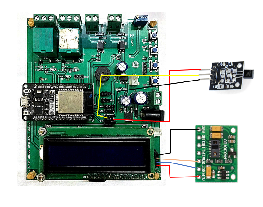
Connection Layout:
| I2C LCD | ||
| LCD | ESP32 BOARD | |
| 1 | SDA | GPIO21 |
| 2 | SCL | GPIO22 |
| 3 | VCC | Vin |
| 4 | GND | GND |
| DTH11 | ||
| DTH | ESP32 BOARD | |
| 1 | OUT | SNS2-D4 |
| 2 | VCC | +3V3 |
| 3 | GND | GND |
| SOIL MOISTURE SENSOR | ||
| SENSOR | ESP32 BOARD | |
| 1 | A0 | P1-D35 |
| 2 | VCC | +3V3 |
| 3 | GND | GND |
| DC-PUMP | ||
| PUMP | ESP32 BOARD | |
| 1 | -ve | GND |
| 2 | +ve | RLY-(NO) |
| 3 | +5V | RLY-(COM) |
Connection Diagram
Procedure:
Step1: Firstly we require all these component connected as per circuit diagram (referred to Fig1).
Step2: The it is require to download and install the Arduino IDE 2.2.1 or above version (link Given Below).
Link: https://www.arduino.cc/en/software
Note: Choose the appropriate version of this software as per your system configuration.
** The Arduino IDE (Integrated Development Environment) is a user-friendly software platform for programming Arduino microcontrollers. Designed for simplicity, it enables users to write, compile, and upload code to Arduino boards seamlessly. With a straightforward interface, the IDE caters to beginners and experienced developers alike, offering a versatile environment for creating interactive electronic projects. It supports C and C++ programming languages, providing a wide range of libraries for various sensors and modules. The Arduino IDE plays a pivotal role in the open-source Arduino ecosystem, fostering innovation and making hardware programming accessible to enthusiasts and professionals in the fields of electronics and IoT.**
Step3: Add Esp32 Board to Arduino IDE that helps us to Program our ESP32 Learning Board with the IDE.
*you can follow the tutorial from Random Nerd to add the ESP32 Board with IDE
Link: https://randomnerdtutorials.com/installing-the-esp32-board-in-arduino-ide-windows-instructions
Courtesy: https://randomnerdtutorials.co *
** The ESP32 is a versatile and powerful microcontroller board widely used in IoT and electronics projects. Developed by Espressif Systems, it features a dual-core processor, Wi-Fi, Bluetooth, and a rich set of peripherals. With its ample processing power and connectivity options, the ESP32 excels in applications ranging from home automation to industrial IoT. The board supports the Arduino IDE and is well-documented, making it accessible for both beginners and experienced developers. Its low power consumption and cost-effectiveness contribute to its popularity, while the integrated capabilities, such as real-time clock and cryptographic functions, enhance its suitability for a broad spectrum of projects.**
Step4: Download and Install CP210x USB to UART Driver to establish the coomnication between ESP32 and System(link given below).
Link: https://www.silabs.com/developers/usb-to-uart-bridge-vcp-drivers
Step5:Go to https://blynk.io and create account or Log in (if already created).
Start doing the following:
Go to Developer Zone AND create a new template and name the project as “SMART PATIENT HEALTH MONITORING SYSTEM” ,Choose hardware as ESP32, connection type as”WIFI”. (shown in fig 2.)

Go to developer zone ->Datastream
Create 3 data streams of type virtual pins with following specifications
- Body Temperature
Pin: V0
Datatype: DOUBLE
Min: 0
Max: 110
Default value: 0
- Pulse
Pin: V1
Datatype: DOUBLE
Min: 0
Max: 200
Default value: 0
- SPIO2
Pin: V2
Datatype: DOUBLE
Min: 0
Max: 100
Default value: 0
Now move to Tab WEB DASHBOARD and drag and drop 3 Gauge and 1Switch as shown in fig3.
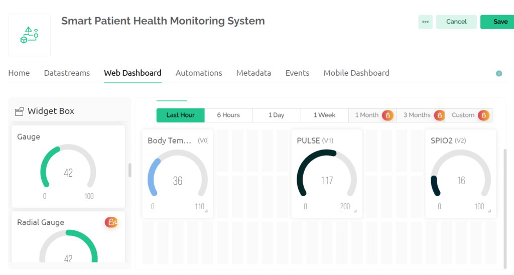
Now Select gauge 1 and name it as Body temperature and choose datastream type as Body Temperature.
Then Select gauge 2 and name it as Pulse and choose datastream type as PULSE .
Then Select gauge 3 and name it as SPIO2 and choose datastream type as SPIO2.
Now Save the changes.
Now go to devices->New devices.->from Templates
Select template as Smart Irrigation System and device name as Smart irrigation system
Then a window pop up copy BLYNK_AUTH_TOKEN from there it is required in code at step 7.
Step6: Install Blynk IOT app in your smart phone.
Link: https://play.google.com/store/apps/details?id=cloud.blynk
Sign in with the same email as in web dashboard.
Select developer option symbol and select template SMART IRRIGATION SYSTEM.
Add 3 GAUGE from Width with Similar configuration in step 5.(Same as done in web dashboard)(reffered to fig 4)
Select each gauge and the switch and choose the respective datastream as done in web dashboard.
//Including all Libraries
#define BLYNK_PRINT Serial
#include <WiFi.h>
#include <WiFiClient.h>
#include <BlynkSimpleEsp32.h>
#include <Wire.h>
#include "MAX30100_PulseOximeter.h"

#define REPORTING_PERIOD_MS     1000

//defining LM35 Sensor pin
#define LM 5

//Credeitials and Authentication password
char auth[] = "***************";  //Enter your Blynk Auth token
char ssid[] = "************";  //Enter your WIFI SSID
char pass[] = "********";
BlynkTimer timer;//Creating object forBlynk Timer

PulseOximeter pox;
uint32_t tsLastReport = 0;

void onBeatDetected()
{

  Serial.println("Beat!!!");

}
//Defining Void Setup
void setup() {
  Serial.begin(115200);
  pinMode(LM,INPUT);
  if (!pox.begin()) {
    Serial.println("FAILED");
    for (;;);
  } else {
    Serial.println("SUCCESS");
  }
  pox.setIRLedCurrent(MAX30100_LED_CURR_7_6MA);

  pox.setOnBeatDetectedCallback(onBeatDetected);


  Blynk.begin(auth, ssid, pass, "blynk.cloud", 80);
  timer.setInterval(100L,update);
}

//creating function to calculate moisture,humidity and Temperature
void update(){
  int h,t,o;

  t = analogRead(LM);
  t=(t*3.3)/4098;
  pox.update();
  if (millis() - tsLastReport > REPORTING_PERIOD_MS) {
    h=pox.getHeartRate();
    o=pox.getSpO2();
  }

  Blynk.virtualWrite(V0,t);
  Blynk.virtualWrite(V1,h);
  Blynk.virtualWrite(V2,o);
}


void loop() {
  Blynk.run();//Run the Blynk library
  timer.run();//Run the Blynk timer
  // put your main code here, to run repeatedly:
}
Include the following libraries:
MAX30100 and BlynkSimpleEsp32
Link: https://drive.google.com/file/d/1G0f3jmk7QdlCM3Izn0scyIrau_dans25/view
Following changes needs to be done in code:
1.Replace auth[] with BLYNK_AUTH_TOKEN copied in step 5.
2.Replace ssid[] with your WiFi ID.
3.Replace pass[] with your WiFi password.
Step7: Upload the codeafter selecting Correct port and board.
Board Name: ESP32 DEV MODULE
Port: Refer to system device manager
Enjoy your project by controlling Smart Patient Management System with Mobile Application and Web Dashboard.
Benefits and Application:
Continuous Monitoring: Allows for remote patient monitoring, reducing the need for frequent hospital visits and improving the quality of life for patients with chronic conditions.
Remote Patient Monitoring: Allows for remote patient monitoring, reducing the need for frequent hospital visits and improving the quality of life for patients with chronic conditions.
Things To Try by Self:
We can ADD multiple sensors for other medical parameter measurement.