
Description About the Project:
A Smart Home Automation System using IoT is a project that integrates Internet of Things technology to enhance the control and monitoring of various devices within a home. This system employs sensors, actuators, and connectivity to create an intelligent network that can be remotely managed via the internet.
Key components and features of an IoT-based Smart Home Automation System may include:
Sensors: Devices like motion detectors, temperature sensors, and door/window sensors gather data about the home environment.
Security Features: Implementations often include security measures for Detection of intruder detection.
Mobile Application: Users can remotely control and monitor their smart home devices through a dedicated mobile app, enabling functions like adjusting thermostat settings, locking/unlocking doors, and managing lighting.
Requirements:
- ESP32 LEARNING BOARD V1.0
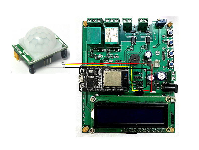
- PIR Motion Sensor
- 12V ADAPTOR
- I2C LCD
Connection Layout:
| I2C LCD | ||
| LCD | ESP32 BOARD | |
| 1 | SDA | GPIO21 |
| 2 | SCL | GPIO22 |
| 3 | VCC | Vin |
| 4 | GND | GND |
| PIR Motion Detection | ||
| PIR | ESP32 BOARD | |
| 1 | OUT | SNS2-D4 |
| 2 | VCC | +3V3 |
| 3 | GND | GND |
Connection diagram:
Procedure:
Step1: Firstly we require all these component connected as per circuit diagram (referred to Fig1).
Step2: The it is require to download and install the Arduino IDE 2.2.1 or above version (link Given Below).
Link: https://www.arduino.cc/en/software
Note: Choose the appropriate version of this software as per your system configuration.
** The Arduino IDE (Integrated Development Environment) is a user-friendly software platform for programming Arduino microcontrollers. Designed for simplicity, it enables users to write, compile, and upload code to Arduino boards seamlessly. With a straightforward interface, the IDE caters to beginners and experienced developers alike, offering a versatile environment for creating interactive electronic projects. It supports C and C++ programming languages, providing a wide range of libraries for various sensors and modules. The Arduino IDE plays a pivotal role in the open-source Arduino ecosystem, fostering innovation and making hardware programming accessible to enthusiasts and professionals in the fields of electronics and IoT.**
Step3: Add Esp32 Board to Arduino IDE that helps us to Program our ESP32 Learning Board with the IDE.
*you can follow the tutorial from Random Nerd to add the ESP32 Board with IDE
Link: https://randomnerdtutorials.com/installing-the-esp32-board-in-arduino-ide-windows-instructions
Courtesy: https://randomnerdtutorials.co *
** The ESP32 is a versatile and powerful microcontroller board widely used in IoT and electronics projects. Developed by Espressif Systems, it features a dual-core processor, Wi-Fi, Bluetooth, and a rich set of peripherals. With its ample processing power and connectivity options, the ESP32 excels in applications ranging from home automation to industrial IoT. The board supports the Arduino IDE and is well-documented, making it accessible for both beginners and experienced developers. Its low power consumption and cost-effectiveness contribute to its popularity, while the integrated capabilities, such as real-time clock and cryptographic functions, enhance its suitability for a broad spectrum of projects.**
Step4: Download and Install CP210x USB to UART Driver to establish the coomnication between ESP32 and System(link given below).
Link: https://www.silabs.com/developers/usb-to-uart-bridge-vcp-drivers
Step5:Go to https://blynk.io and create account or Log in (if already created).
Start doing the following:
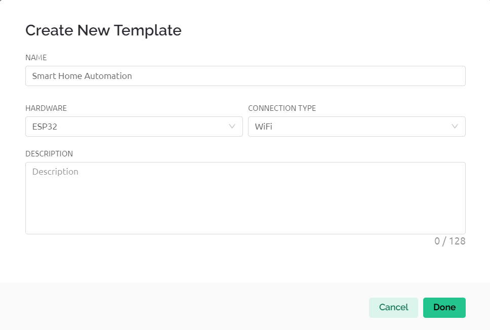
Go to Developer Zone AND create a new template and name the project as “SMART HOME AUTOMATION SYSTEM” ,Choose hardware as ESP32, connection type as”WIFI”. (shown in fig 2.)
Go to developer zone ->Datastream
Create 3 data streams of type virtual pins with following specifications
- Motion Data
Pin: V0
Datatype: INTEGER
Min: 0
Max: 1
Default value: 0
- Device A
Pin: V1
Datatype: INTEGER
Min: 0
Max: 1
Default value: 0
- DEVICE B
Pin: V2
Datatype: INTEGER
Min: 0
Max: 1
Default value: 0
Now move to Tab WEB DASHBOARD and drag and drop 1 Gauge and 2Switch as shown in fig3.
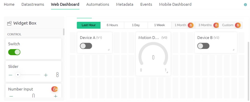
Now Select gauge 1 and name it as Motion Data and choose datastream type as Motion Data
Then Select Switch1 and name it as Button and choose datastream type as DeviceA
Similar for Switch 2.
Now Save the changes.
Now go to devices->New devices.->from Templates
Select template as Smart Irrigation System and device name as Smart irrigation system
Then a window pop up copy BLYNK_AUTH_TOKEN from there it is required in code at step 7.
Step6: Install Blynk IOT app in your smart phone.
Link: https://play.google.com/store/apps/details?id=cloud.blynk
Sign in with the same email as in web dashboard.
Select developer option symbol and select template SMART IRRIGATION SYSTEM.
Add 3 GAUGE and 1 Switch from Width with Similar configuration in step 5.(Same as done in web dashboard)(reffered to fig 4)
Select each gauge and the switch and choose the respective datastream as done in web dashboard.
In Button select mode as switch(additional from web dashboard).
Step7: Program your IDE with the following code:
#define BLYNK_PRINT Serial
#include <WiFi.h>
#include <BlynkSimpleEsp32.h>


char auth[] = "LMuHjSx6PaN0JlFPL7SRy38ppcMBAK55";

char ssid[] = "ONEPLUS";  // type your wifi name
char pass[] = "adit1234";  // type your wifi password

#define PIR_SENSOR  5
BlynkTimer timer;
#define DeviceA 27
#define DeviceB 14
void notifyOnTheft()
{
  int isTheftAlert = digitalRead(PIR_SENSOR);
  Serial.println(isTheftAlert);
  Blynk.virtualWrite(V0,isTheftAlert);
  if (isTheftAlert==1) {
    Serial.println("Theft Alert in Home");

    Blynk.logEvent("Intruder","intruder");

  }
  else if (isTheftAlert==0)
  {

  }
}

void setup(){
  pinMode(PIR_SENSOR, INPUT);
  pinMode(DeviceA,OUTPUT);
  pinMode(DeviceB,OUTPUT);
  Serial.begin(115200);
  Blynk.begin(auth, ssid, pass, "blynk.cloud", 80);
  //dht.begin();
  timer.setInterval(5000L, notifyOnTheft);
}
BLYNK_WRITE(V1){
  int state=param.asInt();
  Serial.println(state);
  digitalWrite(DeviceA,state);
}
BLYNK_WRITE(V2){
  int state=param.asInt();
  Serial.println(state);
  digitalWrite(DeviceB,state);
}

void loop(){
  Blynk.run();
  timer.run();
}
Include the following libraries:
LiquidCrystal_I2C and BlynkSimpleEsp32
Link: https://github.com/blynkkk/blynk-library/releases/tag/v1.3.2
Following changes needs to be done in code:
1.Replace auth[] with BLYNK_AUTH_TOKEN copied in step 5.
2.Replace ssid[] with your WiFi ID.
3.Replace pass[] with your WiFi password.
Step7: Upload the codeafter selecting Correct port and board.
Board Name: ESP32 DEV MODULE
Port: Reffer to system device manager
Enjoy your project by controlling Smart Home Automation System with Mobile Application and Web Dashboard.
Benefits and Application:
Convenience: Automation allows users to control various devices and systems with ease. From adjusting thermostat settings and lighting to managing home security, all can be done remotely through a mobile app or voice commands.
Remote Monitoring: Users can keep an eye on their home even when away, receiving notifications about unusual activities or security breaches. This remote monitoring contributes to peace of mind and quick response to emergencies.
Improved Quality of Life: By streamlining and simplifying daily tasks, a smart home contributes to an improved quality of life. It allows occupants to focus on more meaningful activities and reduces stress associated with managing various aspects of home life.
Things To Try by Self:
ADD DHT Sensor to monitor Temperature and humidity of the surroundings of house.